Parallel Circuit Calculations
Let’s start with a parallel circuit consisting of three resistors and a single battery:
The Principle of Parallel Circuits
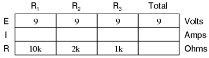
The first principle to understand about parallel circuits is that the voltage is equal across all components in the circuit. This is because there are only two sets of electrically common points in a parallel circuit, and voltage measured between sets of common points must always be the same at any given time. Therefore, in the above circuit, the voltage across R1 is equal to the voltage across R2 which is equal to the voltage across R3 which is equal to the voltage across the battery. This equality of voltages can be represented in another table for our starting values:
Ohm’s Law Applications for Simple Parallel Circuits
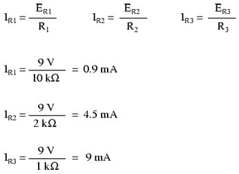
Just as in the case of series circuits, the same caveat for Ohm’s Law applies: values for voltage, current, and resistance must be in the same context in order for the calculations to work correctly. However, in the above example circuit, we can immediately apply Ohm’s Law to each resistor to find its current because we know the voltage across each resistor (9 volts) and the resistance of each resistor:
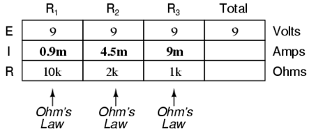
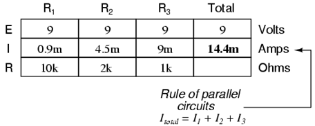
At this point we still don’t know what the total current or total resistance for this parallel circuit is, so we can’t apply Ohm’s Law to the rightmost (“Total”) column. However, if we think carefully about what is happening it should become apparent that the total current must equal the sum of all individual resistor (“branch”) currents:
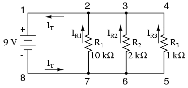
As the total current exits the negative (-) battery terminal at point 8 and travels through the circuit, some of the flow splits off at point 7 to go up through R1, some more splits off at point 6 to go up through R2, and the remainder goes up through R3. Like a river branching into several smaller streams, the combined flow rates of all streams must equal the flow rate of the whole river. The same thing is encountered where the currents through R1, R2, and R3 join to flow back to the positive terminal of the battery (+) toward point 1: the flow of electrons from point 2 to point 1 must equal the sum of the (branch) currents through R1, R2, and R3.
This is the second principle of parallel circuits: the total circuit current is equal to the sum of the individual branch currents. Using this principle, we can fill in the IT spot on our table with the sum of IR1, IR2, and IR3:
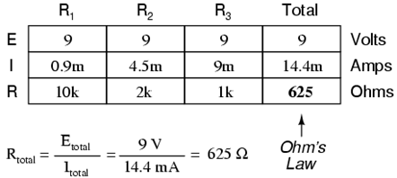
Finally, applying Ohm’s Law to the rightmost (“Total”) column, we can calculate the total circuit resistance:
The Equation for Parallel Circuits
Please note something very important here. The total circuit resistance is only 625 Ω: less than any one of the individual resistors. In the series circuit, where the total resistance was the sum of the individual resistances, the total was bound to be greater than any one of the resistors individually. Here in the parallel circuit, however, the opposite is true: we say that the individual resistances diminish rather than add to make the total. This principle completes our triad of “rules” for parallel circuits, just as series circuits were found to have three rules for voltage, current, and resistance. Mathematically, the relationship between total resistance and individual resistances in a parallel circuit looks like this:
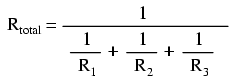
The same basic form of equation works for any number of resistors connected together in parallel, just add as many 1/R terms on the denominator of the fraction as needed to accommodate all parallel resistors in the circuit.
When solving for voltage, current, and resistance in a series-parallel circuit, follow the rules which apply to the series part of the circuit, and follow the rules which apply to the parallel part of the circuit.
Solving these circuits can be simplified by reducing the circuit to a single equivalent resistance circuit, and redrawing the circuit in simplified form. The circuit is then called an equivalent circuit (Figure 46).
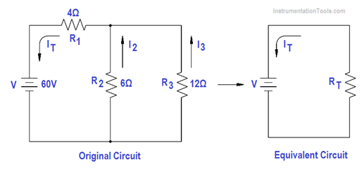
Figure ; Redrawn Circuit Example
The easiest way to solve these types of circuits is to do it in steps.
Step 1: Find the equivalent resistance of the parallel branch:
Rp = (R2 R3 )/(R2+R3)
Rp = (6×12)/(6+12)
Rp = 72/18 = 4Ω
Step 2: Find the resistance of the equivalent series circuit:
RT = R1 +Rp = 4 + 4 = 8Ω
Step 3: Find total current (IT)
IT = V / RT = 60/8 = 7.5 amps
Step 4: Find I2 and I3 . The voltage across R1 and R2 is equal to the applied voltage (V), minus the voltage drop across R1.
V2 = V3 = V – IT R1 = 60 – (7.5 x 4) = 30V
Then, I2 and I3 are calculated.
I2 = V2/R2 = 30/6 = 5 amps
I3 = V3/R3 = 30/12 = 2.5 amps.