Simple Series Circuits
Series circuits: we will outline the three principles you should understand regarding the ciurcuit.
1. Current: The amount of current is the same through any component in a series circuit.
2. Resistance: The total resistance of any series circuit is equal to the sum of the individual resistances.
3. Voltage: The supply voltage in a series circuit is equal to the sum of the individual voltage drops.
Let’s take a look at some examples of series circuits that demonstrate these principles.
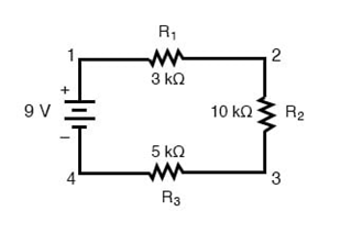
We’ll start with a series circuit consisting of three resistors and a single battery:
The first principle to understand about series circuits is as follows:
The amount of current in a series circuit is the same through any component in the circuit.
This is because there is only one path for current flow in a series circuit. Because electric charge flows through conductors like marbles in a tube, the rate of flow (marble speed) at any point in the circuit (tube) at any specific point in time must be equal.
Using Ohm’s Law in Series Circuits
From the way that the 9-volt battery is arranged, we can tell that the current in this circuit will flow in a clockwise direction, from point 1 to 2 to 3 to 4 and back to 1. However, we have one source of voltage and three resistances. How do we use Ohm’s Law here?
An important caveat to Ohm’s Law is that all quantities (voltage, current, resistance,
and power) must relate to each other in terms of the same two points
in a circuit. We can see this concept in action in the single resistor circuit
example below.
Using Ohm’s Law in a Simple, Single Resistor Circuit
With a single-battery, single-resistor circuit, we could easily calculate any quantity because they all applied to the same two points in the circuit:
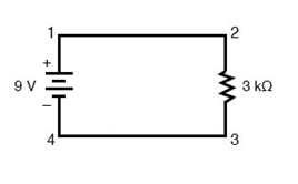
Since points 1 and 2 are connected together with the wire of negligible resistance, as are points 3 and 4, we can say that point 1 is electrically common to point 2, and that point 3 is electrically common to point 4. Since we know we have 9 volts of electromotive force between points 1 and 4 (directly across the battery), and since point 2 is common to point 1 and point 3 common to point 4, we must also have 9 volts between points 2 and 3 (directly across the resistor).
Therefore, we can apply Ohm’s Law (I = E/R) to the current through the resistor, because we know the voltage (E) across the resistor and the resistance (R) of that resistor. All terms (E, I, R) apply to the same two points in the circuit, to that same resistor, so we can use the Ohm’s Law formula with no reservation.
Using Ohm’s Law in Circuits with Multiple Resistors
In circuits containing more than one resistor, we must be careful in how we apply Ohm’s Law. In the three-resistor example circuit below, we know that we have 9 volts between points 1 and 4, which is the amount of electromotive force driving the current through the series combination of R1, R2, and R3. However, we cannot take the value of 9 volts and divide it by 3k, 10k or 5k Ω to try to find a current value, because we don’t know how much voltage is across any one of those resistors, individually.

The figure of 9 volts is a total quantity for the whole circuit, whereas the figures of 3k, 10k, and 5k Ω are individual quantities for individual resistors. If we were to plug a figure for total voltage into an Ohm’s Law equation with a figure for individual resistance, the result would not relate accurately to any quantity in the real circuit.
For R1, Ohm’s Law will relate the amount of voltage across R1 with the current through R1, given R1‘s resistance, 3kΩ:
But, since we don’t know the voltage across R1 (only the total voltage supplied by the battery across the three-resistor series combination) and we don’t know the current through R1, we can’t do any calculations with either formula. The same goes for R2 and R3: we can apply the Ohm’s Law equations if and only if all terms are representative of their respective quantities between the same two points in the circuit.
So what can we do? We know the voltage of the source (9 volts) applied across the series combination of R1, R2, and R3, and we know the resistance of each resistor, but since those quantities aren’t in the same context, we can’t use Ohm’s Law to determine the circuit current. If only we knew what the total resistance was for the circuit: then we could calculate the total current with our figure for total voltage (I=E/R).
Combining Multiple Resistors into an Equivalent Total Resistor
This brings us to the second principle of series circuits:
The total resistance of any series circuit is equal to the sum of the individual resistances.
This should make intuitive sense: the more resistors in series that the current must flow through, the more difficult it will be for the current to flow.
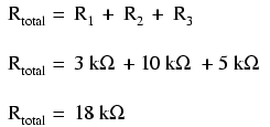
In the example problem, we had a 3 kΩ, 10 kΩ, and 5 kΩ resistors in series, giving us a total resistance of 18 kΩ:
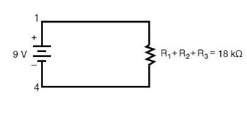
In essence, we’ve calculated the equivalent resistance of R1, R2, and R3 combined. Knowing this, we could redraw the circuit with a single equivalent resistor representing the series combination of R1, R2, and R3:
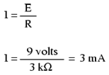
Calculating Circuit Current Using Ohm’s Law
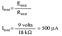
Now we have all the necessary information to calculate circuit current because we have the voltage between points 1 and 4 (9 volts) and the resistance between points 1 and 4 (18 kΩ):
Calculating Component Voltages Using Ohm’s Law
Knowing that current is equal through all components of a series circuit (and we just determined the current through the battery), we can go back to our original circuit schematic and note the current through each component:
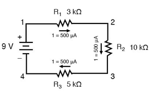
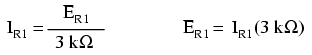
Now that we know the amount of current through each resistor, we can use Ohm’s Law to determine the voltage drop across each one (applying Ohm’s Law in its proper context):
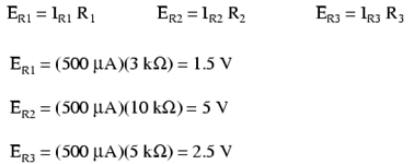
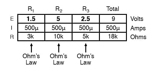
Notice the voltage drops across each resistor, and how the sum of the voltage drops (1.5 + 5 + 2.5) is equal to the battery (supply) voltage: 9 volts.
This is the third principle of series circuits:
The supply voltage in a series circuit is equal to the sum of the individual voltage drops.
Analyzing Simple Series Circuits with the “Table Method” and Ohm’s Law
However, the method we just used to analyze this simple series circuit can be streamlined for better understanding. By using a table to list all voltages, currents, and resistance in the circuit, it becomes very easy to see which of those quantities can be properly related in any Ohm’s Law equation:
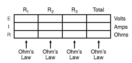
The rule with such a table is to apply Ohm’s Law only to the values within each vertical column. For instance, ER1 only with IR1 and R1; ER2 only with IR2 and R2; etc. You begin your analysis by filling in those elements of the table that are given to you from the beginning:
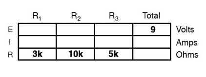
As you can see from the arrangement of the data, we can’t apply the 9
volts of ET (total voltage) to any of the resistances (R1, R2, or R3) in any Ohm’s Law formula because
they’re in different columns. The 9 volts of battery voltage is not applied directly across R1, R2, or R3. However, we can use our “rules” of
series circuits to fill in blank spots on a horizontal row. In this case, we
can use the series rule of resistances to determine a total resistance from
the sum of individual resistances: 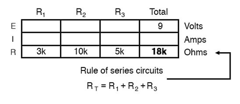
Now, with a value for total resistance inserted into the rightmost (“Total”) column, we can apply Ohm’s Law of I=E/R to total voltage and total resistance to arrive at a total current of 500 µA:
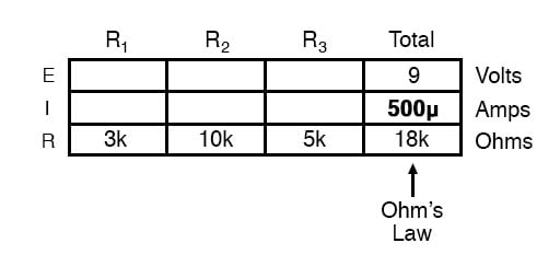
Then, knowing that the current is shared equally by all components of a
series circuit (another “rule” of series circuits), we can fill in the currents
for each resistor from the current figure just calculated: 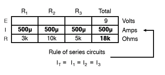
Finally, we can use Ohm’s Law to determine the voltage drop across each resistor, one column at a time:
Let’s briefly summarize the major features of resistors in series:
1. Series resistances add together to get the equivalent resistance:
Req = R1 + R2 + R3 + R4…
2. The same current flows through each resistor in series.
3. Individual resistors in series do not get the total source voltage, but divide it. The total potential drop across a series configuration of resistors is equal to the sum of the potential drops across each resistor.