TRANSFORMER AND FORMULAS
Basic of a transformer
TRANSFORMERS
Transformers generally, are devices capable of converting quantities from one value to the other. For this Article, we will be focusing on the Voltage transformer which is a static electrical component capable of converting AC voltage from one value to the other without changing the frequency using the principles of electromagnetic induction.
In one of our previous articles on the Alternating current, we mentioned how important the transformer was, in the history of the alternating current. It was the major enabler that made the alternating current possible. Initially when DC-based systems were being used, they could not be transferred over long distances due to power loss in the lines as distance (length) increases, which means DC power stations had to be placed everywhere, thus the main goal of AC was to solve the transmission issue and without the transformer, that wouldn't have been possible as the losses would still have existed even with AC.
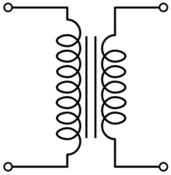
Single Phase Transformer
With the transformer in place, AC could be transmitted from the generating stations at a very high voltage but low current which eliminates the losses in the line(wires) due to the value of I2R (which gives the power loss in a line). The transformer is then used to convert the high voltage, low current energy to Low voltage, high current energy for final distribution within a community without changing the frequency and at the same power that was transmitted from the generating station (P= IV).
To better
understand the voltage transformer, it is best to use its most simplified model
which is the single-phase transformer.
Single Phase Transformer
The single phase transformer is the most common (in terms of numbers in use) kind of voltage transformers. It is present in most of the “plugged in” appliances we use at home and everywhere else.
It is used to describe the operation principle, construction etc of a
transformer because other transformers are like a variation or modification of
the single phase transformer. For example, certain people refer to the
three-phase transformer as being made up of 3 single phase transformers.
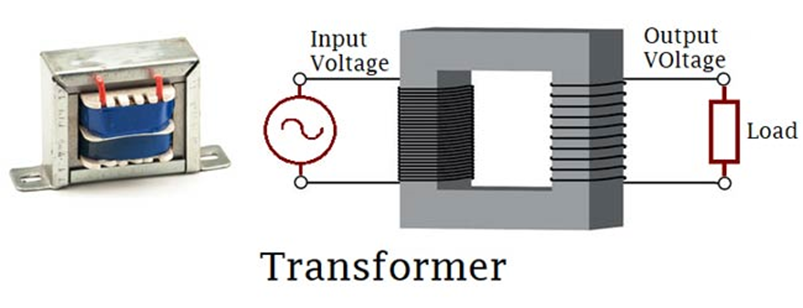
Single Phase Transformer is made up of two coils/winding (The primary and the secondary coil). This two winding are arranged in such a way that there exists no electrical connection between them, thus they are wound around a common magnetic Iron generally referred to as the transformer’s core, thus the two coils only have a magnetic connection between them. This ensures that power is transmitted only via electromagnetic induction and also makes the transformers useful for Isolating connections.
Operational Principle of Transformer:
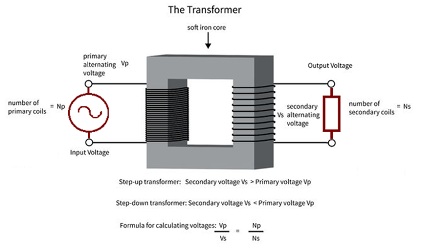
As earlier mentioned, the transformer consists of two coils; the primary and the secondary coils. The primary coil always represents the input to the transformer while the secondary coil, the output from the transformer.
Two main effects define the operation of the transformer:
The first
is that, a current flowing through a wire sets up a magnetic field
around the wire. The magnitude of the resulting magnetic field is always
directly proportional to the amount of current passing through the wire. The
magnitude of the magnetic field is increased, if the wire is wound into a
coil-like form. This is the principle with which magnetism is induced by the
primary coil. By applying a voltage to the primary coil, it induces a
magnetic field around the core of the transformer.
The second effect which when combined with the first explains the operational principle of the transformer which is based on the fact that, if a conductor is wound around a piece of magnet and the magnetic field changes, the change in magnetic field will induce a current in the conductor, the magnitude of which will be determined by the number of turns of the conductor coil. This is the principle with which the secondary coil gets energized.
When a voltage is
applied to the primary coil, it creates a magnetic field around the core the
strength depends on the applied current. The created magnetic field thus
induces a current in the secondary coil which is a function of the magnitude of
the magnetic field and the numbers of turns of the secondary coil.
This operational principle of the transformer also explains why the AC had to be invented because the transformer will only work when there is an alternation in the applied voltage or current as only then will the electromagnetic induction principles work. Thus the transformer couldn’t be used for DC then.
Construction of the Transformer
Basically, a transformer is made up of two parts which include; two inductive coils and a laminated steel core. The coils are insulated from each other and also insulated to prevent contact with the core.
The construction of the transformer will thus be examined under the coil and core construction.
Transformer’s Core
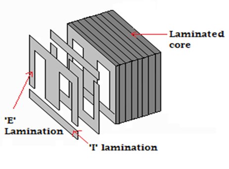
The core of the transformer is always constructed by stacking laminated sheets of steel together, ensuring a minimum air-gap exists between them. The transformers core in recent times is always made up of laminated steel core instead of iron cores to reduce losses due to eddy current.
There are three major shapes of the laminated steel sheets to choose from, which are E, I, and L.
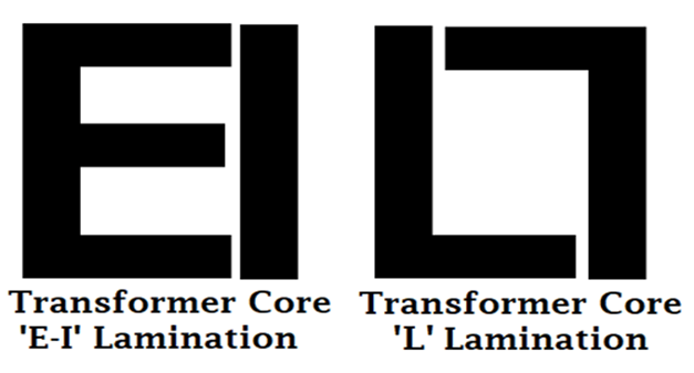
When stacking the lamination together to form the core, they are always stacked in such a way that the sides of the joint are alternated. For example, of the sheets are assembled as front faced during the first assembly, they will be back faced for the next assembly as shown in the image below. This is done to prevent high reluctance at the joints.
Coil
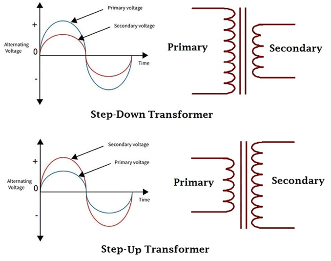
When constructing a transformer, it becomes very important to specify the type of transformer as either step up or step down as this determines the number of turns that will exist in the primary or secondary coil.
Types of Transformers:
Majorly there are three types of voltage transformers;
1. Step Down Transformers
2. Step Up Transformers
3.IsolationTransformers
The step-down transformers are transformers which gives a reduced value of the voltage applied to the primary coil at the secondary coil, while for a step up transformer, the transformer gives an increased value of the voltage applied to the primary coil, at the secondary coil.
Isolation transformers are transformers which gives the same voltage applied to the primary at the secondary and thus basically used to isolate electrical circuits.
From the above explanation, creating a particular type of transformer
can only be achieved by designing the number of turns in each of the primary
and secondary coils to give the required output, this can thus be determined by
the turns ratio. You can read through the linked tutorial to learn more about
the different types of transformers.
Transformer Turns Ratio and EMF Equation:
The transformer turns ratio is given by the equation;
n = Np/Ns = Vp/Vs
where n = turns ratio
Np = Number of turns in primary coil
Ns = Number of turns in secondary coil
Vp = Voltage applied to the primary
Vs = Voltage at the secondary
These relationship described above can be used to calculate each of the parameters in the equation.
The formula above is known as the transformers voltage action.
Since we said the power remains the same after transformation then;
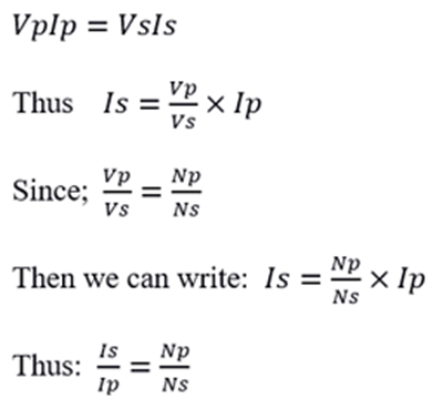
This formula above is referred to as the transformer's current action. Which serves as proof that the transformer not only transforms voltage but also transforms current.
https://circuitdigest.com/tutorial/transformer-basics
Exercises
|
1 |
A transformer has 200 turns on its primary coil, and 50 on its secondary coil. This is a:- |
||
|
Step-up transformer |
|||
|
Step-down transformer |
|||
|
|
|||
|
2 |
A
transformer has a primary coil of 100 turns and a secondary coil of 300
turns. |
||
|
300V |
|||
|
33V |
|||
|
60V |
|||
|
40V |
|||
|
|
|||
|
3 |
If we need to change 240 V down to 12 V, and our transformer to has 2000 turns on its primary coil, how many turns should it have on its secondary coil? |
||
|
100 turns |
|||
|
240 turns |
|||
|
12 turns |
|||
|
2880 turns |
|||
|
|
|||
|
4 |
The
mains voltage varies from country to country. |
||
|
Made for U.K. |
|||
|
Made for Kludge |
|||